4. Configuration
4.1. Update to latest firmware
Update all components to the latest firmware version:
GX devices: Venus OS v2.15 or newer.
Updating a CCGX from v1.74 to a newer version requires a one time manual upgrade. It can’t be done automatically. Instructions to upgrade to v2.00 can be found here.
Multi, MultiGrid, MultiPlus or Quattro: 422 or newer. Update using VictronConnect (download the VictronConnect configuration guide for VE.Bus products here) or use Remote VE.Bus firmware updates.
Solar chargers, either VE.Can or VE.Direct, must run their latest firmware version.
For firmware files and instructions, see the Firmware section in Victron Professional.
4.2. MultiPlus/Quattro and ESS Assistant
Settings that need to be made in VEConfigure:
Grid tab: configure the country code. A password is required: ask your supplier. More information in VEConfigure: grid codes & loss of mains detection.
Note: If you leave this setting as 'None', the system will not supply battery energy to support local AC loads when the grid is connected. You do need to change this setting even if it is your intention not to export DC energy to the grid.
Add the ESS Assistant: How to add an Assistant from start to finish
General tab: The ESS Assistant will have the integrated battery monitor of the MultiPlus/Quattro activated. Leave it activated (!) even if there is a BMV or a smart CAN-bus-connected battery in the system.
Charger tab: The ESS Assistant will have already selected the proper battery type, as well as disabled the Storage mode. Verify and where necessary change the rest of the settings: charge voltages & maximum charge current.
Note that, for systems with the ESS Assistant installed, the MPPT solar chargers will follow the charge curve as set in VEConfigure. The charge parameters configured in the MPPT solar chargers are ignored in an ESS setup.
Configure all the other settings.
Notes with regards to the input current-limit and PowerAssist:
Input current-limiter setting: The configured limit is used as the threshold for AC current at the AC-in of the Multi/Quattro. Further notice that:
Loads in parallel with the Multi/Quattro are not taken into account: therefore, install all loads on the AC-out of the Multi or Quattro in systems that require AC input current limiter functionality, for example, systems with a small AC load connected.
The current limiter will be used for both directions of the current.
The PowerAssist setting in VEConfigure3 will be disabled and ignored when ESS is installed.
Dynamic current limiter: The dynamic current limiter in VEConfigure3 will be disabled and ignored when ESS is installed.
Notes relating to low battery warning levels:
The low battery warning is active when the battery voltage drops below the dynamic cut-off level plus the restart offset, which defaults to 1.2 Volt for a 48V system. Just like the cut-off voltage, the warning voltage level is also dynamic.
There is no hysteresis: the warning will disappear when the voltage rises again.
During this warning, also called a pre-alarm, the red LED on the Multi will blink, and optionally the GX device will show a notification. For most ESS systems its recommended to disable that notification on the GX device. See FAQ Q5.
The related parameters on the inverter tab, ie. the DC input- low shut-down, restart and pre-alarm levels do not apply. They are ignored when the ESS Assistant is installed.
General notes:
PV power coming from a grid-tie inverter, either connected in parallel or on AC-out, will be used to charge the battery. Charge current and other charge parameters are configured on the charger tab in VEConfigure3.
Make sure to keep the lithium batteries checkbox on the charger page consistent with the battery choice in the Assistant.
When using a VE.Bus BMS and a Multi Compact, check the DIP switches: DIP switch 1 must be on, and DIP switch 2 must be off.
4.3. ESS settings in the GX device
Navigate to Settings → ESS, to see this menu:

4.3.1. Mode
Optimized (with BatteryLife) and Optimized (without BatteryLife)
At times when there is excess PV power, the PV energy is stored in the battery. That stored energy is then used later, to power the loads at times when there is a shortage of PV power.
Keep batteries charged
Failures of the utility grid are the only periods at which the battery will be discharged. Once the grid is restored, the batteries will be recharged with power from the grid, and of course also solar, when available.
External control
The ESS control algorithms are disabled. Use this when self-implementing a control loop. More information.
BatteryLife
For details on BatteryLife operation, see Chapter 6.2. In short, enable BatteryLife for these technologies:
OPzV, OPzS
GEL / AGM
Victron 12.8V Lithium batteries, and other lithium batteries that have passive cell balancing
Because it makes no sense to leave a battery discharged, without reserve power in case of mains failure, we recommend leaving BatteryLife enabled on the following battery technologies, too:
Lithium with active cell balancing
However, BatteryLife can be disabled in these cases.
4.3.2. Grid metering
Select External meter if an external meter such as an EM540 is installed, otherwise leave the setting as Inverter/Charger.
All loads and (optional) grid-tie inverters must be installed on the AC out in a system without a Victron grid meter. See earlier in the manual for more information.
4.3.3. Inverter AC output in use
Setting this to 'Disabled' hides the AC-out graphic in the overview pane. Use this in systems where there is nothing connected to the output of the Multi or Quattro, which is typical for certain grid-parallel systems in Western Europe.
4.3.4. Self-consumption from battery

This setting allows ESS only to use battery power for essential loads. It also allows battery banks to be sized to get critical loads through the night without the battery being discharged into the non-essential loads.
This is relevant for ESS systems with:
A grid meter
Quite significant non-essential loads
Feed-in disabled
Setting options are:
All system loads (default)
Only critical loads
This menu item is only visible if 'Inverter AC output in use' is enabled.
4.3.5. Feed-in excess solar charger power
Set to 'On' to make the solar charger always operate at its maximum power point. The first priority is powering the loads, and the second priority is to charge the battery. If more power is available when those two priorities are met, then that power will be fed to the utility grid.
Please note that when enabling this option, the DVCC charge current limit configured under Settings → Limit charge current won't be active. The solar charger will operate at full power for maximum feed-in into the grid. It's advisable to configure a safe limit on the solar chargers when used with a small battery bank.
4.3.6. Multiphase regulation
See chapter 7.
4.3.7. Minimum SoC (unless grid fails)
Configurable minimum SoC limit. Either with or without BatteryLife enabled, ESS will drop loads once the SoC has fallen to the configured setting - except when the utility grid has failed and the system is in Inverter mode. In this case it will continue discharging the battery until one of the other thresholds have been met. See chapter 6.1 for more information.
4.3.8. Peak shaving

(Applies only when BatteryLife is enabled - it is always on in 'Keep batteries charged mode')
Using the Peak Shaving option it is possible to always let the system keep PowerAssisting when the loads exceed the AC input current limit and it is required, or only above the Minimum SOC parameter.
As soon as the peak is over, it will recharge the battery using power from the grid, while still prioritising solar.
Note that there is a 5% hysteresis; If the Minimum SOC is set to 50%, it will then start recharging back to that 50% only once (by peak shaving) the battery has dropped to 45%.
Also note that this works for the critical loads on the AC output only, not those connected to an energy meter.
The default setting when using the Optimised modes is 'Above minimum SOC only.' Use this option in systems that do not perform peak shaving.
4.3.9. Active SoC limit
(Applies only when BatteryLife is enabled)
This % shows the maximum usable capacity of the system - which will never be more than 80%.
Use this setting to see the current BatteryLife SoC level.
4.3.10. BatteryLife state
The different BatteryLife states are:
Self-consumption: normal operation - discharging allowed.
Discharge disabled: the battery has been discharged to the actual SoC limit. (The state will return to self-consumption whenever the SoC rises 5% above the set limit).
Slow charge: ESS will slowly charge the battery when the SoC has been below the actual SoC limit for more than 24 hours. It will keep slow charging until the lower limit has been reached at which point the system once again switches to Discharge disabled.
Sustain: the Multi/Quattro has gone into sustain mode after the battery voltage has reached the dynamic cut-off voltage during discharge.
Recharge: ESS will recharge the battery to the minimum SoC limit if it drops more than 5% below the minimum configured SoC. Once the minimum SoC is reached the system once again switches to Discharge disabled.
4.3.11. Limit inverter power
Limit the power drawn by the Multi: ie. limit the power being inverted from DC to AC.
Notes:
The losses in the inverter/charger are not taken into account. If you want to limit the amount of power being drawn from the battery, you will have to set this limit slightly lower to compensate for those losses.
Power coming from the MPPTs is not taken into account. Using this feature in a system with MPPTs can cause the output power from the MPPT to be reduced.
This limit is with respect to power drawn from the battery and will affect the total of all phases.
This limit only applies while connected to AC-in: In inverter mode, the AC loads determine how much power is drawn from the battery.
4.3.12. Grid setpoint
This sets the point at which power is taken from the grid when the installation is in self-consumption mode. Setting this value slightly above 0W prevents the system from feeding back power to the grid when there is a bit of over-shoot in the regulation. The default value is therefore 50W - but should be set to a higher value on large systems.
4.3.13. Grid feed-in

The grid feed-in can be controlled via this menu. It enables the AC and/or DC-coupled PV feed-in to be completely deactivated or the maximum feed-in power to be limited.
Feed-in will only occur if there is sufficient surplus PV production to fully supply the loads, and the battery is charged (or at it's charge current limit).
The Feed-in limiting active status indicator shows 'Yes' only if the feed-in limiting is currently working. In all other cases, the status is displayed as 'No'.
Note: The limit system feed-in is a system target, and under some circumstances such as large load disconnection, or sudden increase in solar production, it may be exceeded momentarily until the system is able to regulate the inverter output back to within the target limit.
4.3.14. AC-coupled PV - Zero and limited feed-in with Fronius AC PV
The AC-Coupled PV zero or limited feed-in feature is specifically designed and most rigorously tested with Fronius AC PV inverters.
The earliest Fronius firmware version which can be used is 3.7.3-2
If there is more than one Fronius PV Inverter present in the system, they will all be limited
Zero feed-in is not supported on Fronius IG Plus inverters.
Change the following settings in the Fronius web interface:
In the Fronius setup menu, set Data export via Modbus to tcp.
In the same menu, set Sunspec Model Type to int + SF
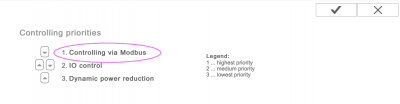
In Settings→DNO Editor, make sure that in the 'Controlling Priorities' section that 'Controlling via Modbus' is set to be priority 1.
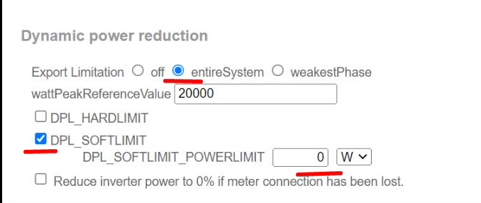
Note In Settings→DNO Editor, the default setting for Dynamic Power Reduction is 'No limit/off'. If you wish for the Fronius to stop generating if communications are lost (and no longer receiving instructions from Modbus control), then additionally "Dynamic Power Reduction" also needs to be configured.
For this behaviour - set Export Limitation to entireSystem, and DPL_SOFTLIMIT_POWERLIMIT to the export power limit (or 0).
Then double check that all above criteria are met. It will show Feed-in limiting active No if the firmware requirement; the Data export; or the Sunspec Model type settings are incorrect, or the units are shut down (no available PV), or AC-input is disconnected / unavailable.
When working correctly, Feed-in limiting active will show Yes
Do not use a Fronius Smart Meter for limiting export when part of a Victron ESS System. More details about when a Fronius Smart Meter can, and can not, be used is explained here.
4.4. GX device - Scheduled charge levels
4.4.1. Introduction

The Scheduled charge levels setting is located in the ESS menu of the GX device. It allows you to set up to five scheduled periods, during which the system will take power from the grid to charge the battery. This is typically used to charge the battery during off-peak tariff time windows (TOU). For each schedule, configure a start time, the duration, a SoC limit (target) and the self-consumption limit behaviour.
How does it work?
If a SoC limit is set for a scheduled window, charging will stop when the batteries reach the requested SoC.
If Self-consumption above limit is set to PV, the battery will not be discharged until the scheduled window ends, but available PV will be used for powering loads.
If Self-consumption above limit is set to PV & Battery, the battery will be discharged for self-consumption up to the SoC limit, after which only PV will be used.
By intelligently creating the charge slots, for example a scheduled charge slot with a lower SoC target following another slot with a higher SoC target, the system allows power from the battery to be used until it reaches the lower state of charge.
This also enables more flexible planning of the charge slots in the event of scheduled outages (load shedding schedules). For example, if there is a scheduled outage at 8pm and again at 4am, you can recharge after the 8pm outage, but not after the 4am outage (since the sun will be up soon and PV takes over).
4.4.2. Configuration
Scheduled charge levels is available as part of ESS. It is accessible on the GX device menus under Settings → ESS. It is only available when the ESS mode is set to Optimised. Scheduled charge levels naturally makes no sense when the mode is set to Keep Batteries Charged.
You can see at a glance what is configured, with a summary of the start day, time and duration shown for each.


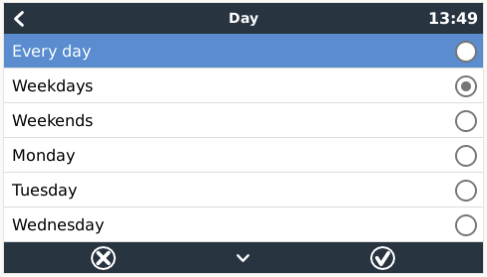
For each schedule you can select a specific day of the week, every day of the week, or you may opt to charge on all weekdays or only on weekends.
 |
The Multi will start charging from the grid at the specified start time, and stop after the set duration or when the set SoC limit is reached. The period designated by the day, start time and duration will subsequently be referred to as a scheduled charge window.
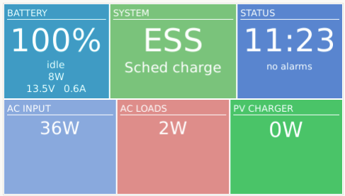
During charging, the ESS state will indicate that Scheduled charge levels is in progress.

4.4.3. Stop charge on SoC
When a SoC limit is set for a scheduled charge window, charging will stop when the batteries reach the requested SoC.
4.5. GX device - Other settings
4.5.1. Settings -> System setup -> AC Input types
Set the AC Input type to Generator when connected to a generator. The system will then enable generator-charging and correctly load the generator when running.
Note that we recommend wiring the Generator to AC-in 1, and the Grid to AC-in 2. The reason is that the Quattro will then prioritize the Generator over the Grid. That arrangement offers maximum flexibility (allowing forced generator intervention even when the grid is available) and maximises control.
4.5.2. Generator start/stop settings
More information on controlling remote generator start/stop is available here.
4.6. MPPT solar charger
In ESS, the MPPT solar chargers will follow the charge curve as set in VEConfigure. The charge parameters configured in the MPPT solar chargers themselves are ignored in an ESS setup.
The Charge current, however, still needs to be configured in the MPPTs.
MPPT with VE.Direct port
No special configuration is necessary.
MPPT with VE.Can port
No special configuration is necessary. Make sure the Device instance is configured to 0 (the default). MPPTs in the VE.Can network configured to a different Device instance will not be managed by ESS.
4.7. Understanding LED Codes During ESS Operation
When a Multi is working parallel to the grid (as it is during ESS mode) the Mains and Inverter LEDs indicate the direction of the power flow. The following table describes the corresponding LED codes, including combinations not specific to parallel grid operation. All other LED indications are not covered here and can be found in the corresponding inverter/charger manual.
Mains and Inverter LED states | Description and Power direction |
|---|---|
 | Energy to battery (like normal charging) |
 | Power towards the loads (similar to PowerAssist) |
 | Around balance point |
 | Power towards the grid |
Remaining combinations not specific to parallel to the grid operation | |
 | The unit is in charger-only mode but is stil off. Grid voltage is detected but has not yet been accepted |
 | Slave (LEDs blinking slowly and alternating) |
 | Unit is off |
 | Inverter mode |
 | LED on LED blinking LED off |